Shielding Windows
Think Schlegel EMI for Shielding – Shielded Windows
As the originator of the fabric-clad foam EMI shielding technology, Schlegel EMI is the industry’s most trusted name. We continue to set the standard for quality and innovation, designing advanced solutions for a wide range of applications. And our worldwide locations ensure that you get what you need, when you need it.
Modern electronic equipment often requires EMI Gaskets to avoid radiating EMI/RFI suspeptibility to outside sources of EMI/RFI. Maintaining electromagnetic compatibility can be an increasing challenge of the designers of today’s electronic and electrical products.
Schlegel Electronic Materials, Inc. (SEM), the preeminent manufacturer of fabric over foam EMI shielding products for the computer, telecommunications, and electronic industries, offers a full range of EMI shielding products–including gaskets, I/O backplane shielding gaskets, and highly conductive envelopes, tapes and laminates.
SEM is now proud to introduce a complete line of quality Shielded Windows. The addition to SEM’s extensive portfolio of shielding products allows SEM to be your exclusive EMI shielding supplier, to help you meet or exceed your global requirements for electromagnetic compatibilty (EMC).
Design and Consultation
SEM can offer a design and consultation service to help you to design filters for your display requirements. Displays are used in all applications from public information, through to man machine interfaces. This means that the physical properties of a filter will vary to suit its performance needs.
Consideration will often need to be given to several characteristics, including: impact resistance, solvent and abrasion resistance, reflection control, fire specifications, U.V. resistance or protection, RFI shielding, ESD, anti – static and anti – mist.
Filters can be designed to incorporate several characteristics in one part, and material selected from allyl carbonate, acrylic, polycarbonate, polyester and glass.
If a filter is designed correctly it can reduce cost, improve the readability of the display and allow your product to look at it’s best for a long time.
A display filter is the part of your equipment, which is looked at for the majority of its life. If badly designed it can have a detrimental effect on the performance of your product.
Optical Filters and Fascia Panels
SEM supplies high quality optical filters and fascia panels. These products are manufactured to suit individual customer requirements or specifications and can be made from allyl carbonate, acrylic, polycarbonate and glass. All filters can be manufactured to include screen printing and RFI shielding, (see technical information “RFI / EMC Filter windows” if necessary).
Filters can be manufactured to include many characteristics including ; contrast enhancement, reflection control, impact strength, fire specifications, abrasion and solvent resistance, polarisation and combinations of properties.
Products
Shielded filter windows are designed for use with electronic displays and give a high level of shielding from both internally and externally generated electromagnetic emissions. These windows can be designed to incorporate any of the filter characteristics described in the “Optical Filters and Fascia Panels” data sheet.
RFI / EMC shielded windows can be manufactured in allyl carbonate, acrylic, polycarbonate or glass. The shielding element is either a cast in micro – fine mesh (allyl carbonate only), laminated micro – fine mesh or ITO deposition.
Cast Allyl Carbonate Embedded Mesh Windows.
These shielded windows offer the superb screening performance of micro – fine mesh, combined with the outstanding characteristics of allyl carbonate (see “Optical Filters and Fascia Panels” for details on allyl carbonate).
The general properties of cast windows are:
- Micro – fine mesh is cast in to a one piece sheet, therefore no delamination problems and higher temperature specification than laminated parts.
- They can be machined to any desired profile, with or without rebates.
- Extremely good abrasion, solvent, impact and heat resistance.
- Light weight.
- Different meshes available to suit the application and mesh is blackened to reduce reflections.
- None reflective surfaces can be cast in.
- Mesh can be set at any desired angle.
- Silver loaded bus – bar termination.
This product is cast from ADC monomer ( allyl diglycol carbonate ) and has a series of properties, which makes it ideal for the production of filter windows and fascia panels. This material is equivalent to CR39.
Properties include:
- Less than half the weight of glass
- Bright surfaces and light transmissions close to optical glass
- Refractive index close to that of crown glass
- High impact strength
- Remarkable abrasion resistance ( approximately 20 times that of acrylic )
- Resistance to pitting from hot metal sparks, 30 – 40 times higher than glass and other plastics
- Excellent resistance to acids, alkalis and to all solvents including aliphatic and aromatic hydrocarbons
- Easy surface dying
- Better scratch resistance than hard coated plastics
- Resistance to distortion by temperatures up to 130 ° C, a temperature at which acrylic resins are melted
- U.V. absorbers can be added to help protect LCD displays in strong sunlight
Allyl carbonate can be cast from 1 mm thick upwards
Optical Properties | ASTM test method | |
|---|---|---|
Yellowness Index | 0.73 | D 1925 |
Haze, % | 0.21 | D 1003 |
Refractive Index, n.20 | D 1.50 | D 542 |
Dispersion Factor | 57 | D 542 |
Visible Transmission, % | 93.3 | D 1003 |
Ultraviolet Transmission, % | ||
( 3 mm thickness) | ||
at 300 nm. | 25 | |
at 340 nm. | 77 | |
at 380 nm. | 88 |
Physical and mechanical properties | ASTM test method | |
|---|---|---|
Density, g/cc | 1.311 | D 792 |
Tensile Modulus, (Mpa) | 2.4 | D 638 |
Taber Abrasion, ( x P.M.M.A.) | 20 | D 1044 |
(modified) | ||
Rockwell Hardness, (M) | 97 | D 785 |
IZOD Impact Resistance KJ/mq. | 7.85 | D 256 |
(Unnotched at 23 C) | (modified) |
Chemical resistance | ASTM test method | |
|---|---|---|
7 days immersion at 23 C | ||
Water : | ||
absorption, % | 0.4 | |
haze variation, % | 0.07 | |
Acetone : | ||
absorption, % | 0.78 | |
haze variation, % | 0 | |
Toluene : | ||
absorption, % | 0.4 | |
haze variation, % | 0 | |
Ethyl Alcohol 95% : | ||
absorption, % | 0.1 | |
haze variation, % | 0.05 | |
Trichloroethylene : | ||
absorption, % | 0.04 | |
haze variation, % | 0.06 | |
H.D.T. 1,82 Mpa, C | 69 | D 64 |
Thermal expansion | |
|---|---|
Linear coeff./ C | |
from -40 to 25 C | 0.81 x 10⁻⁴ |
from 25 to 75 C | 1.20 x 10⁻⁴ |
from 75 to 125 C | 1.43 x 10⁻⁴ |
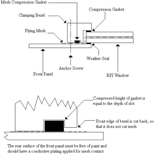
These shielded windows again offer the superb screening performance of micro – fine mesh, which in this version can be left flying for direct termination to the equipment screen. Material and characteristics for the filter can be selected from the full range,
(see “Optical Filters and Fascia Panels” for details of the filter range).
The general properties of laminated windows are:
- Micro – fine mesh is laminated in between your selected filter medium.
- Plastic versions can be machined to any desired profile, and glass versions can be constructed with or without rebates.
- Different meshes available to suit the application and mesh is blackened to reduce reflections.
- None reflective surfaces can be included.
- Mesh can be set at any desired angle.
- Various termination methods are available including; tape edge, mesh over gasket, flying mesh, silver bus – bar.
Shielded Windows

Indium Tin Oxide ( ITO ), is a transparent semiconductor which can be coated onto optical filter materials. ITO benefits over metal depositions because it is more transparent and less reflective, for a given impedance level. A good ITO coating will have optical transmission levels of greater than 75 %.
The ITO coating can be sputtered onto glass or plastic and has good chemical and mechanical durability. It will also not oxidize when exposed to air.
The oxygen content of the coating is adjusted to a compromise point, giving good optical transparency and low impedance, normally between 10 – 40 Ohms / square for shielding.
The shielding effect of thin film coatings is due to reflection of the electromagnetic wave. This means that the coatings are only effective when the wave impedance is greater than the coating impedance. This in turn means that the coatings have no effect in the magnetic, or H – Field, and are not suitable for all applications. There can also be some optical limitations to ITO coated windows and these should be fully discussed before selection is made.
Performance of an ITO window will depend on its impedance and the field impedance, but generally will produce between 80 and 120 dB attenuation in the E – Field, and around 20 dB for Plane waves.
Polycarbonate is usually used when impact strength or fire retardance is required. These filters are made from proprietary sheet material and normally coated with a hard coat to give abrasion and solvent resistance.
There are only a few standard tints available for polycarbonate, but others can be produced when necessary, in relatively small volumes. We have several techniques available to enable the production of polycarbonate contrast enhancement filters.
Properties of the polycarbonate will depend on the selected grade.
Glass Filters.
Glass filters can be produced plane, matt etched or with multilayer AR coating. These filters can also be toughened when required. Laminations can be built to include all fi ltering characteristics already mentioned.
Available Coatings For Acrylic and Polycarbonate
A range of optical coatings are available for the surfaces of acrylic and polycarbonate filters. Coatings can offer a selection of the following characteristics ;
- Abrasion resistance
- Solvent resistance
- Anti – glare ( matt coating )
- Anti – mist
- Anti – Newton ring
- Multi – layer anti – refl ective ( limited to a small range of product )
Acrylic filters are often used for larger displays and also where contrast enhancement is required ( due to the large range of tints available ). For these filters we use a high grade cast acrylic which can be obtained down to 0.5 mm thick.
The large range of tints available allows specific wavelengths to be transmitted. This can be used to contrast enhance, color correct or produce band pass filters. Infra-red filters are also manufactured to block visible light and transmit IR at around 90%.
All acrylic filters can be finished with a hard coat, for abrasion and solvent resistance, which can be applied as a gloss or matt surface.
Optical Properties | |
|---|---|
Refractive Index nD20 | 1.492 |
Light Transmission % | 92 |
Physical and mechanical properties | |
Density, g/cc | 1.18 |
Tensile Strength N/mm2 | 75 |
Elongation at Break % | 4.5 |
Bending Strength N/mm2 | 135 |
Notched Impact Strength | 2 |
Modulus of Elasticity N/mm2 | 3300 |
Thermal Characteristics | |
Linear coeff./ C 0 – 50 ° C | 70 x 10-6 |
Vicat softening point ° C | 100 |
Temp for continuous use ° C | 70 |
Performance and Specifications
The performance of any RFI / EMC window is dependent on how well it is bonded to the equipment screen. The following tables show the screening capability of the mesh, where the mesh itself is clamped to the screen with no gaskets in between.The shielding performance will improve as the window size reduces, due to the performance characteristics of the aperture. Mesh selection should be based on required performance and with the way that it interacts with your chosen display.
SHIELDING PERFORMANCE (dB ATTENUATION)
Test Window 300 x 300 mm
Openings | Wire | E | FIELD | PLANE | WAVE | ||||
|---|---|---|---|---|---|---|---|---|---|
Mesh | per inch | diameter | 1 MHz | 10 MHz | 100 MHz | 100 MHz | 400 MHz | 1 GHz | 10 GHz |
Copper | 100 | 0.001 | 90 | 90 | 70 | 50 | 20 | ||
Copper | 100 | 0.002 | 107 | 111 | 85 | 70 | 70 | 58 | |
Stainless | 50 | 0.002 | 94 | 90 | 82 | 58 | 55 | 28 | |
Stainless | 80 | 0.001 | 106 | 88 | 82 | 64 | 60 | 34 | |
Stainless | 100 | 0.001 | 128 | 112 | 92 | 77 | 80 | 86 | 74 |
Stainless | 80 x 60 | 0.001 | 102 | 105 | 103 | 75 | 60 | 43 |
Test Window 1000 x 1000 mm for BLK / Cu / 100 opi / 0.002 / 90º
Frequency | Mode | ITO (dB) | Single Mesh (dB) | Double Mesh (dB) |
|---|---|---|---|---|
100 KHz | E | – | 98 | 123 |
1 MHz | E | – | 93 | 152 |
10 MHz | E | 32 | 78 | 124 |
100 MHz | E | 28 | 65 | 111 |
400 MHz | P | 32 | 60 | 115 |
1 GHz | P | 28 | 50 | 94 |
10 GHz | P | 24 | – | 67 |
Test methods used were consistent with MIL – STD – 285
The about test results are for guidance only
Cast allyl carbonate is a high quality substrate for optical filters. However this is still a plastic material, and although at SEM we take every care in its production, blemishes do occur. These blemishes take the form of small inclusions and fine, trapped fibres. So that SEM can quantify the quality of products made from allyl carbonate, it is important to lay down a specification and inspection criteria. This is a specification that we feel is obtainable and repeatable, when viewed against our past performance. With individual project discussions, it may be possible to tighten up the specification, but this will be done by inspecting out defects and will have obvious implications on price.
Inspection Conditions.
The panel should be viewed from the front face under daylight conditions, with normal non-directional lighting. Viewing should take 15 seconds and from a distance of 450 mm.
Blemishes.
SIZE | CRITERIA (Window Area) | CRITERIA (Non Window Area) |
|---|---|---|
<0.15 mm | Disregard | Disregard |
0.15 – 0.3 mm | 1 per 100 x 100 mm | 2 per 100 x 100 mm |
0.3 – 0.5 mm | 0 per panel | 1 per panel |
0.5 – 0.75 | 0 per panel | 0 per panel |
Small Fibres.
Small fibres in cast allyl carbonate are not like the surface fibres in coated material. In coatings the fibre creates an inclusion on the surface which is highly visible. With the cast product fibres are very fine and are trapped within the material. These are difficult to see and do not produce a surface defect. These fibres are only visible when illuminated with a direct, bright light and do not effect the quality of a display.
Scratching.
No scratching is allowed on the panels.
Summary.
Please be assured that we will attempt to produce the best quality panels that we can at all times. This specification is an indication of worst case conditions
Due to the application methods of hard coatings on plastic substrates, blemishes do occur. These blemishes take the form of coating inclusions, trapped fibres and exaggerated material defects. So that SEM can work with these products, it is important to lay down a specification and inspection criteria. This is a specification which we feel is obtainable and repeatable, when viewed against past performance of coating suppliers. With individual project discussions, it may be possible to tighten up the specification, but this will be done by inspecting out defects and will have obvious implications on price.
Inspection Conditions.
The panel should be viewed from the front face under daylight conditions, with normal non-directional lighting. Viewing should take 15 seconds and from a distance of 450 mm.
Blemishes.
SIZE | CRITERIA (Window Area) | CRITERIA (Non Window Area) |
|---|---|---|
<0.15 mm | Disregard | Disregard |
0.15 – 0.3 mm | 5 per 100 x 100 mm | 5 per 100 x 100 mm |
0.3 – 0.5 mm | 1 per panel | 2 per panel |
0.5 – 0.75 | 0 per panel | 1 per panel |
Small Fibre | 1 per panel | 3 per panel |
Scratching.
Where polycarbonate panels are used, fine scratching will be inevitable on the rear surface. These marks can be caused by wiping with the softest of cloths, and even though they are extremely fine, they can look obvious when illuminated.
For panels larger than 100 mm square, only one scratch allowed on the front face if less than 10 mm long.
Summary.
Please be assured that we will attempt to produce the best quality panels that we can from hard coated material. This specification is an indication of worst case conditions, allowing for our suppliers current quality.
SEM supply cast filters from allyl diglycol carbonate ( ADC monomer ). The following information details the burning characteristics of the cast polymer. These details have been obtained from a variety of sources, including the manufacturer of the monomer, but no certification is available for these results. All details are given for information purposes only and if certification is required an independent test will need to be carried out.
UL Fire Rating
Polymer cast from ADC has been tested in America and has passed UL94 HB at 1 mm and 1.5 mm thickness. This test requires a flame spread of less than 75 mm / minute for less than 3 mm thick, or less than 40 mm / minute for greater than 3 mm. Other flame spread tests back up this result.
Flame Spread
For 1.3 – 2.9 mm thick – to ASTM D 635 – < 25 mm
For 4 mm thick – result from monomer manufacturer – 25 mm
Limiting Oxygen Index
Any oxygen index below 21 % means that the material will burn in air. This polymer has an index of 18.3 %. This is slightly better than acrylic at about 17 % but worse than polycarbonate at 25 %.
Self Ignition Temperature
Self-ignition temperature is 720 º F according to ASTM D 1929.
Products of Burning
If the polymer is 100 % burned, the products are CO2 and H2O. The products of incomplete combustion will also include some CO, propene and some soot with phenolic end groups on the surface. (OH attached to aromatic ring ). Toxic substances are not expected.
Stability
Unlike some other optical plastics on fire, this polymer does not drip burning material.
Independent Testing
SEM will supply samples to any customer wishing to carry out independent testing.
General Description
This is a highly conductive coating deposited on a transparent polyester film. It is available in rolls 30” wide by 15’ long, the usable width is 28” or it can be supplied cut to size via a specific drawing. The Conductive coating is overcoated with a ceramic type film which serves to increase visible light transmission and to provide a protective barrier that exhibits electrical conductivity through the layer.
Application Information
This product is designed for electrical and planewave shielding, grounding and static discharge applications. The film is used as a transparent, shielding panel for visual displays in instrumentation equipment, control panels, computer processing, printers and large electrode displays as a grounding shield.
Mounting Options
Affixed to a conductive mating surface with clamps or Bonded with a conductive adhesive or a double sided Conductive tape
Mounted between a substrate and conductive mounting Surface with or without the aid of edge bonding to the substrate
Material Description
- Substrate: polyester film .005 in (0.13mm) thick, clear and colourless
- Conductive Coating: Vacuum deposited thin metal film with protective ceramic coating
- Standard Bulk Material Part Number 90-00119
Performance Characteristics
- Substrate and Coating Surface Resistivity: 14 ohms/sq(nominal) (+/- 4 ohms/sq)
- Visible Light Transmission: 70 to 80%
- Temperature Range: -60°C to 150° C
EMEI Global Network

Emei Materials Systems Limited
Unit 5, 3/F., Block A, New Trade Plaza,
6 On Ping Street, Shatin, N.T., HK
Tel :+852-2428 7878
Fax :+852-2686 8268
Email : ems@emeigroup.com / emhpsalesco1@emeigroup.com
Website : https://www.emeigroup.com/
Dongguan Emei Materials Systems Limited
No.8, QiaoxinRoad, QiaotouDongguan, Guangdong, P.R. China
Postal Code : 523525
Tel :+86-769-8334 1628/13809624596
Fax :+852-2686 8268
Email : ems@emeigroup.com / emhpsalesco1@emeigroup.com
Website : https://www.emeigroup.com/
Emei Materials Systems (Shanghai) Limited
4/F, 79 Parts, 111 Meisheng Road, F.T.Z., Pudong, Shanghai, China
Postal Code : 200131
Tel :+86-21 5868 3381
Fax :+86-21 5868 3386

SCHLEGEL ELECTRONIC MATERIALS ASIA LIMITED
Unit 5, 3/F., Block A, New Trade Plaza,
6 On Ping Street, Shatin, N.T., HK
Visit Us
Tel :+852-2686 8168
Fax :+852-2686 8268
Email : emeihk@emeigroup.com
Website : https://www.emeigroup.com/
SCHLEGEL (DONGGUAN) ELECTRONICS LIMITED
No.8A Qiaoxin Road, Qiaotou Dongguan, Guangdong, P.R. China
Visit Us
Postal Code : 523525
Tel :+86-769-8334 1628
Fax :+86-769-8334 2028
Email : emeidg@emeigroup.com
Website : https://www.emeigroup.com/
SCHLEGEL (SHANGHAI) ELECTRONICS LIMITED
4/F, 79 Parts,111 Meisheng Road, F. T. Z., Pudong, Shanghai, China
Postal Code : 200131
Tel :+86-21-5868 3383
Fax :+86-21-5868 3386
Email : emeish@emeigroup.com
Website : https://www.emeigroup.com/
TAIWAN SCHLEGEL ELECTRONICS LIMITED
No. 99, Alley 3, Lane 182,
Section 2 Wenhua Road, Banqiao District, Taiwan R.O.C
Tel :+886-2-8258 5148
Fax :+886-2-8258 5149
Email : emeitw@emeigroup.com
Website : https://www.emeigroup.com/
Schlegel Electronic Materials Inc.
1555 Jefferson Road, Rochester, NY 14623
Tel :+1 585-643-2000
Fax :+1 585-427-7216
Email : schlegelemi.na@schlegelemi.com
Website : https://www.schlegelemi.com/
Schlegel Electronic Materials Belgium bv
Schatting 73 BE-8210 Zedelgem Belgium
Tel :+32 59-560-270
Fax :+32 59-560-271
Email : schlegelbe@schlegelemi.com
Website : https://www.schlegelemi.com/

EMEI (HK) COMPONENTS LIMITED
Unit 5, 3/F., Block A, New Trade Plaza,
6 On Ping Street, Shatin, N.T., HK
Tel :+852-2686 8118
Fax :+852-2686 8128
Email : eclsales@emeigroup.com
Website : https://www.emeigroup.com/
DONGGUAN EMEI COMPONENTS LIMITED
No.8 Qiaoxin Road, Qiaotou Dongguan, Guangdong, P.R. China
Postal Code : 523525
Tel :+86-769-8334 8480
Fax :+86-769-8334 2028
Website : https://www.emeigroup.com/

BMC FAR EAST LIMITED
Unit 5, 3/F., Block A, New Trade Plaza,
6 On Ping Street, Shatin, N.T., HK
Tel :+852-2637 8822
Fax :+852-2686 8128
Email : bmcfe@emeigroup.com
Website : https://www.emeigroup.com/
BMC DONGGUAN LIMITED
No.8 Qiaoxin Road, Qiaotou Dongguan, Guangdong, P.R. China
Postal Code : 523525
Tel :+86-769-8345 2480
Fax :+86-769-8334 5656
Website : https://www.emeigroup.com/
Contact Us
Address
Unit 1, 3/F., Block A, New Trade Plaza,
6 On Ping Street, Shatin, N.T.,HK
- +852-2686 8168
- +852-2686 8268
- emeihk@emeigroup.com
